Gree Versati III in Home Assistant: ESPHome Modbus Guide, A to Z

This post may contain affiliate links. As an Amazon Associate we earn from qualifying purchases. Disclosure.
The Gree Versati III has a Modbus port behind its wired controller. An ESP32 and a cheap RS485 module turn it into a local Home Assistant device, no cloud needed.
Quick take: The Gree Versati III has a Modbus RTU port on the back of its wired touch controller. An ESP32 with a TTL-to-RS485 module (about $15-25 in parts) turns it into a local, cloud-free Home Assistant device: every temperature, compressor speed, error flag and setpoint Gree documents, including mode, hot water target, weather curve and power limit. The config in this guide covers the full register map from Gree's own Modbus document, validates and compiles on ESPHome 2026.9, and fixes the single most common reason writes fail: Versati only accepts "write multiple" commands.
The Gree+ app works, but it is a cloud app with a handful of controls. Home Assistant's built-in Gree integration targets air conditioners, so a Versati shows up with the wrong entities, and the newer local Wi-Fi integration exposes only a water setpoint so far. If you want the heat pump inside your automations (solar surplus, tariffs, alerts), the wired Modbus route is the reliable one.
This guide takes you from an empty desk to a working device: parts, wiring, the port on the controller, flashing, first readings, safe writes and two useful automations.
What Do You End Up With?
Everything below comes from Gree's "MODBUS [VERSATI III]" protocol document (version 01, 2021-08-09). The config exposes:
- 24 sensors: outdoor, flow, return, hot water tank, discharge, suction, defrost, economizer and refrigerant line temperatures, compressor target and actual frequency, the weather-curve target, plus flow-minus-return delta T computed on the ESP.
- 33 setpoints: water and room setpoints for heating and cooling, hot water, power limit (0.1 kW steps), current limit, both weather curves, hysteresis values, backup heater and other heat source switch-on temperatures, disinfection and screed drying.
- 9 selects: on/off, mode (heat, hot water, cool, and the combined modes), backup heater stages, room thermostat type, force mode, air purge and heat source logic.
- 23 switches: quiet mode, weather-dependent mode, fast hot water, disinfection, holiday mode, hot water priority, timers, gate control and more.
- 76 binary sensors: compressor, fan, defrost, heaters, internal pump and 3-way valve states, plus every protection and drive error Gree lists, and one combined Fault entity for notifications.
- 2 buttons: Reset error, and a restart for the bridge itself.
What Do You Need Before You Start?
Check your model. This guide is for the Versati III family (split, monobloc and all-in-one) with the white touch wired controller. Versati II and IV use different documentation. Cooper & Hunter UNITERM 3 units appear to share the same register map, based on a community fork that ships the Versati III document.
Know the risks. You will open the wired controller and connect a cable to its communication port. Do it with the heat pump powered off at the breaker. Do not touch anything inside the indoor unit's electrical box; nothing in this project requires it. If your unit is under warranty or you are not comfortable with this, ask your installer.
Skills needed: basic jumper wiring, installing an add-on in Home Assistant, and editing a YAML file. No soldering is strictly required, though Gree recommends soldering and insulating the port connection for long-term reliability.
What Parts Do You Need?
| Part | Why | Approx. cost |
|---|---|---|
| ESP32 dev board with an ESP-WROOM-32 module (ESP32-DevKitC or a 38-pin clone) | Runs ESPHome, bridges Modbus to Wi-Fi | $8-12 |
| TTL-to-RS485 module: auto-direction with 3.3 V logic, or a MAX485 board with an EN pin | Converts the ESP's UART to the RS485 bus | $3-25 |
| 5 V USB power supply (2 A or more) and a USB data cable that fits your board (USB-C on mine, micro-USB on older DevKitC boards) | Powers the ESP32; the same cable flashes it | $5-10 |
| 4 female-to-female jumper wires | ESP32 to RS485 module | $2 |
| Shielded twisted pair (FTP Cat 5e works) | Controller to RS485 module | by the meter |
| 2-pin connector with leads to fit the controller's BMS port | The port ships empty | $1-2 |
| Small enclosure (optional) | Keeps the boards tidy near the controller | $5 |
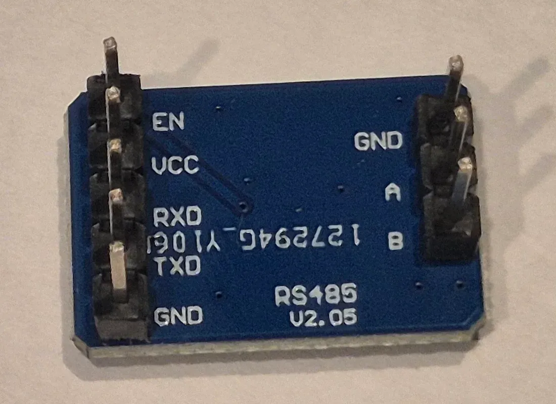
On the RS485 module: two kinds work. An auto-direction module (often labeled only TXD and RXD, 3.3 V logic) needs no extra wire, and the config's default assumes it. A MAX485 board like the one in my photos has an EN pin that switches between sending and receiving, so it needs one more wire to the ESP32 and one uncommented line in the config. The listing for mine names a MAX485 chip, a 4.75 to 5.25 V supply, 2.54 mm header pins and a 19.4 x 13.4 x 11.2 mm board, and it cost about 12 zloty. The ESP32 board (USB-C, CH340 USB chip, 4 MB flash, 52 x 28.5 mm) cost about 24 zloty at a Polish electronics shop. An isolated module, such as Waveshare's TTL TO RS485 with galvanic isolation, adds protection for the heat pump's electronics; a cheap non-isolated board also works for a short cable inside one building.
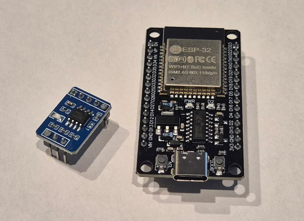
On the connector: the port's pitch is not documented. Measure it before ordering (2.0 mm and 2.5 mm are the usual suspects). The author of one community project reports his plug needed trimming to fit.
Where Is the Modbus Port on the Controller?
Gree calls it the BMS communication interface. It is on the back of the wired touch controller, not on the indoor unit's main board.
- Switch the heat pump off at the breaker.
- Remove the controller from its wall plate or the front of the indoor unit.
- Look for an empty two-pin socket. A four-wire cable is already plugged into the controller; leave it alone, it is Gree's internal link to the main board.
Gree's pinout for the BMS socket:
| BMS pin | Signal |
|---|---|
| 1 | B |
| 2 | A |
Two things not to use: the CN4 connector on the main board (it carries the controller's internal protocol) and the H1/H2 terminals some Gree units have (also a proprietary bus, not Modbus).
While the controller is in your hand, check its address: Commissioning menu > Address. The default is 1. Gree says never to use 0 or 126. Leave it at 1 unless you have several units.
How Do You Wire It?
Two wiring variants follow, because the RS485 module decides the details. Variant A is an auto-direction module with 3.3 V logic. Variant B is the MAX485 board with an EN pin that I used. If your module has no EN pin, follow A.
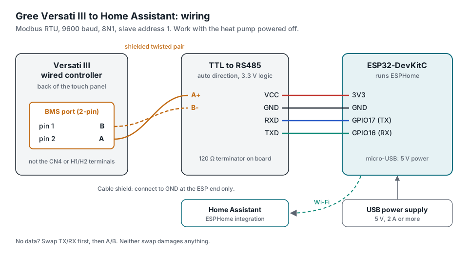
Variant A: auto-direction module, 3.3 V logic
| ESP32 | RS485 module | Versati controller (BMS port) |
|---|---|---|
| 3V3 | VCC | |
| GND | GND | |
| GPIO17 (TX) | RXD | |
| GPIO16 (RX) | TXD | |
| A+ | pin 2 (A) | |
| B- | pin 1 (B) |
Variant B: MAX485 module with an EN pin
The module in my photos is printed RS485 V2.05. Its 5-pin header reads EN, VCC, RXD, TXD and GND, and the 3-pin side reads GND, A and B. RXD and TXD are named from the module's point of view, which is why the ESP32's TX pin goes to RXD. Wire it like this:
| ESP32 pin (silkscreen) | Module pin | What it carries |
|---|---|---|
| VIN | VCC | 5 V power |
| GND | GND (5-pin side) | common ground |
| D17 (GPIO17, TX) | RXD | ESP32 to bus |
| D16 (GPIO16, RX) | TXD, through a 1 k and 2 k divider | bus to ESP32 |
| D4 (GPIO4) | EN | direction: high sends, low receives |
| Module pin | Versati controller (BMS port) |
|---|---|
| A | pin 2 (A) |
| B | pin 1 (B) |
The GND pin on the 3-pin side stays unused.
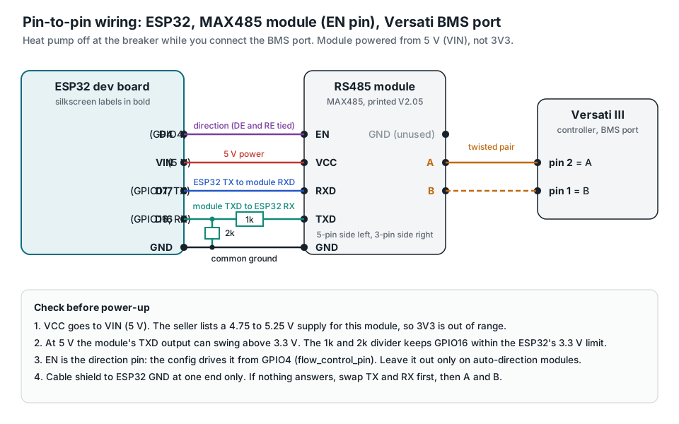
Three details in that table matter:
- VCC comes from VIN, not 3V3. The listing gives a 4.75 to 5.25 V supply for this module, and VIN carries the 5 V from the USB port.
- The TXD line gets a divider. A MAX485 powered from 5 V can drive its output above the 3.3 V the ESP32 pins tolerate. Put 1 k between the module's TXD and D16, and 2 k from D16 to GND. I did not measure the output on my board; the two resistors protect the pin either way.
- EN is the direction input. A bare MAX485 switches between sending and receiving with its DE and RE pins, and one EN pin on a module like this points to those two being tied together. The config drives it from GPIO4: uncomment
flow_control_pin: GPIO4in themodbus:block.
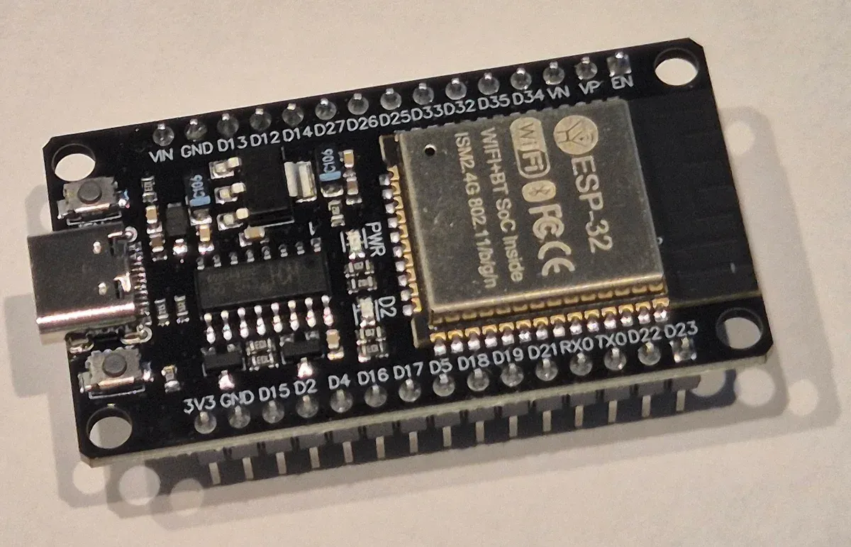
ESP32 boards print GPIO numbers as D-numbers. GPIO17 is D17, GPIO16 is D16 and GPIO4 is D4, all on the lower header next to each other (D4, D16, D17), and 3V3 and GND are the first two pins of that same row. VIN is the first pin of the top row. Leave RX0 and TX0 alone; they belong to the USB serial link.
Rules for both variants
A few rules that save debugging time:
- Use shielded twisted pair for the controller-to-module run, one pair for A and B. Connect the shield to GND at the ESP end only. Community builds without shielding report "Modbus CRC Check Failed" errors.
- Terminate the bus once with 120 ohm across A and B. Most modules have this resistor on board, sometimes behind a jumper or solder pad. On a run of a few meters it rarely matters; if you see CRC errors, toggle it.
- Power the ESP32 from its own USB supply. A USB charger is isolated from mains, which keeps ground loops away from the controller.
- Mislabeled modules are common. If nothing answers, swap TX and RX first, then A and B. Neither swap damages anything.
Bus settings, per Gree: 9600 baud, 8 data bits, no parity, 1 stop bit, Modbus RTU.
How Do You Install ESPHome and Flash the ESP32?
1. Install ESPHome Device Builder
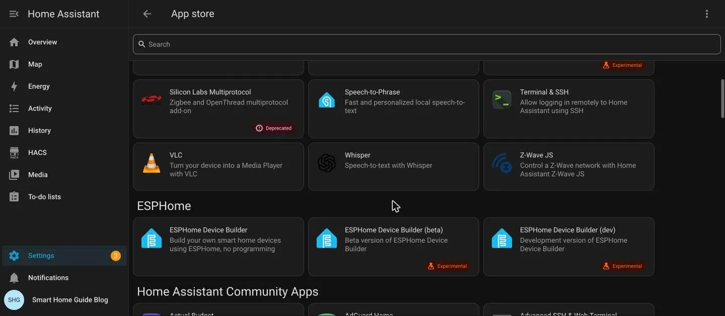
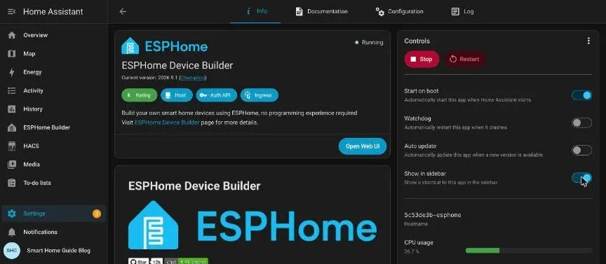
In Home Assistant go to Settings > Apps, click Install app and pick ESPHome Device Builder from the ESPHome section of the store. Home Assistant renamed add-ons to "apps" in 2026, so older versions call the same screen Settings > Add-ons > Add-on store. Click Install, wait for it to finish (a minute or two on a Pi 5), then press Start and switch on Show in sidebar.
I ran every step in this section on Home Assistant OS 18.3 with Core 2026.10.1, ESPHome Device Builder 1.14.9 and ESPHome 2026.9.1. The first time you open the builder it shows a short welcome wizard; Maybe later on the guided tour is fine.
2. Create the device
Open ESPHome Builder from the sidebar and click Create device. The guided Create new project path starts from a board picker and a starter kit, which is more than you need here. Open Advanced set up options instead, choose Empty Configuration, name it versati-modbus and click Finish setup. ESPHome writes a stub YAML for an ESP32 dev module and opens the editor; ignore the "Install now" banner for the moment.
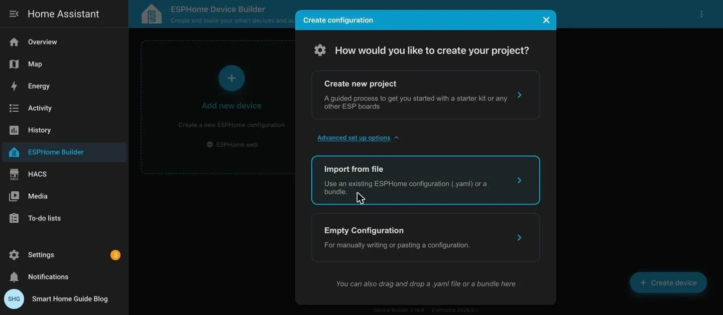
The empty configuration does not generate an API encryption key. Make one yourself with openssl rand -base64 32 (or the key generator on the ESPHome API component page) and keep it for the next step. If you took the guided path, the key already exists under the device card's Show encryption key menu entry.
3. Add your secrets
In ESPHome Builder open the three-dot menu at the top right and choose Secrets. A fresh install has none ("No secrets yet"). Click Add secret, or switch to the { } YAML view and add these four:
wifi_ssid: "YourNetwork"
wifi_password: "YourPassword"
ap_password: "fallback-hotspot-password"
api_key: "the-key-ESPHome-generated-for-this-device"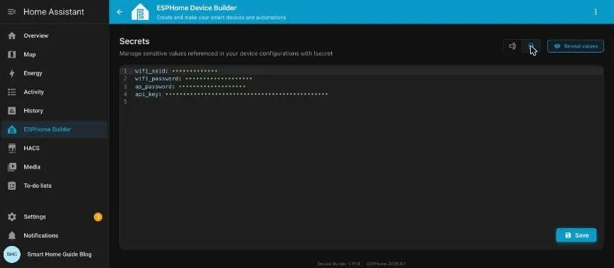
4. Paste the configuration
Open the new device with Edit and replace the YAML in the right-hand editor with the full configuration. Do this after the secrets exist: with the file pasted and no api_key secret, the editor shows Secret 'api_key' not defined and Save asks you to confirm. Download the full config: gree-versati-iii-esphome.yaml (about 1,700 lines). Its core looks like this:
substitutions:
  name: versati-modbus
  friendly_name: Versati
  modbus_address: "1"
  temp_scale: "0.1"   # see "First readings" below

esp32:
  board: esp32dev

uart:
  id: mod_bus
  tx_pin: GPIO17
  rx_pin: GPIO16
  baud_rate: 9600
  data_bits: 8
  parity: NONE
  stop_bits: 1

modbus:
  id: modbus_versati
  uart_id: mod_bus
  send_wait_time: 200ms
  turnaround_time: 100ms
  # flow_control_pin: GPIO4   # uncomment for a MAX485 board with an EN pin on D4

modbus_controller:
  - id: versati            # live states, every 15 s
    address: ${modbus_address}
    modbus_id: modbus_versati
    update_interval: 15s
  - id: versati_slow       # setpoints and config, every 2 min
    address: ${modbus_address}
    modbus_id: modbus_versati
    update_interval: 120s

sensor:
  - platform: modbus_controller
    modbus_controller_id: versati
    name: "Outdoor temperature"
    address: 118
    register_type: holding
    value_type: S_WORD
    unit_of_measurement: "\xB0C"
    device_class: temperature
    filters:
      - multiply: ${temp_scale}

number:
  - platform: modbus_controller
    modbus_controller_id: versati_slow
    name: "Water heating setpoint"
    address: 10
    value_type: U_WORD
    use_write_multiple: true   # Versati rejects single-register writes
    min_value: 20
    max_value: 60
    step: 1
    unit_of_measurement: "\xB0C"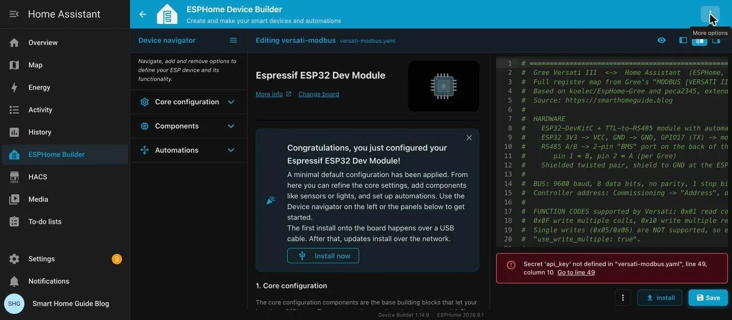
Before you flash anything, open the three-dot menu next to the Install button in the editor and click Validate. The log ends with Configuration is valid! when the secrets and the YAML agree. I got exactly that on the full file, with all 1,746 lines pasted unchanged.
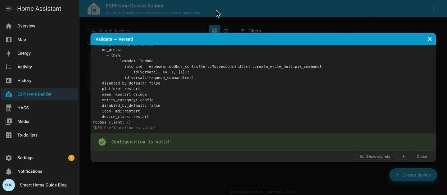
The full configuration compiles to 971,072 bytes (about 0.9 MB) against the 1.8 MB application slot of a 4 MB board, so over-the-air updates have room to work.
5. Flash the first time over USB
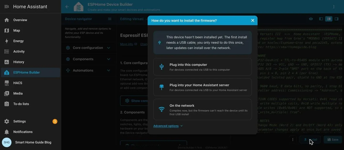
Plug the ESP32 into a USB port with a data-capable cable. Two places work. If the board sits in your own computer, click Install > Plug into this computer (it uses Web Serial, so Chrome or Edge). If it sits in the machine that runs Home Assistant, click Install > Plug into your Home Assistant server. I used the second route: the board went into a USB port of the Pi 5, and the builder compiled and flashed it without my laptop doing anything. The computer route is the same install with a browser port picker instead.
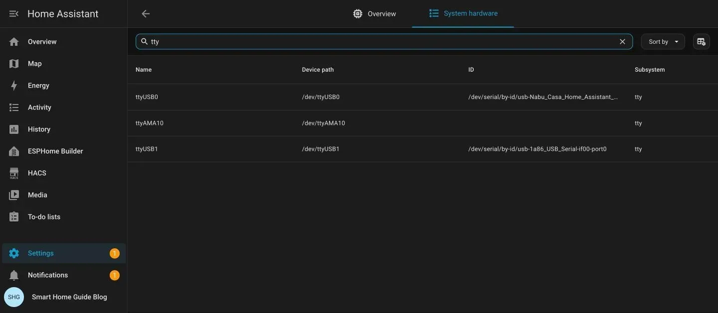
Before you click, check that the server actually sees the board. Under Settings > System > Hardware > All hardware, filtering for "tty" showed my Zigbee stick as /dev/ttyUSB0 and, after I plugged the ESP32 in, a new /dev/ttyUSB1 with the ID usb-1a86_USB_Serial. That's the CH340 chip on the board. No driver is needed on the Pi, the kernel already knows it.
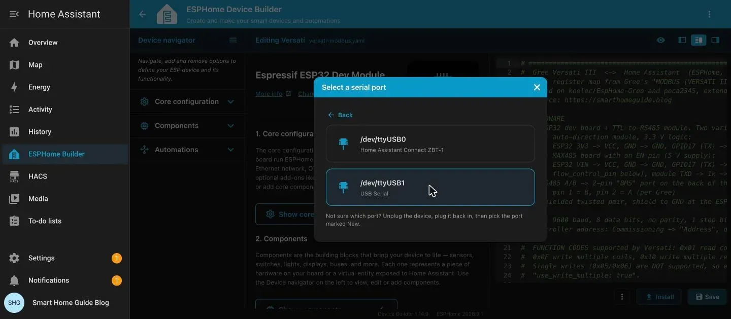
The server route then asks for a serial port. Mine listed two: /dev/ttyUSB0, the Home Assistant Connect ZBT-1, and /dev/ttyUSB1, plain "USB Serial". Pick the one that isn't a dongle you already use. If you can't tell, unplug the board, plug it back in and choose the entry marked New.
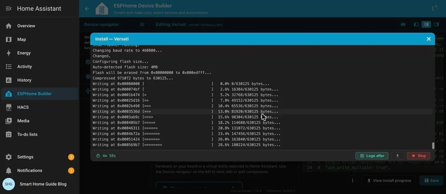
The first install is the slow one. The Pi downloads the ESP-IDF framework (about a minute and a half), compiles 966 build steps (about three minutes) and then writes the flash. From click to reboot it took me five and a half minutes. Later builds reuse the cache and finish far sooner. In the flash log the tool detected 4 MB of flash and squeezed the 971,072-byte image to 630,125 bytes on the way in.
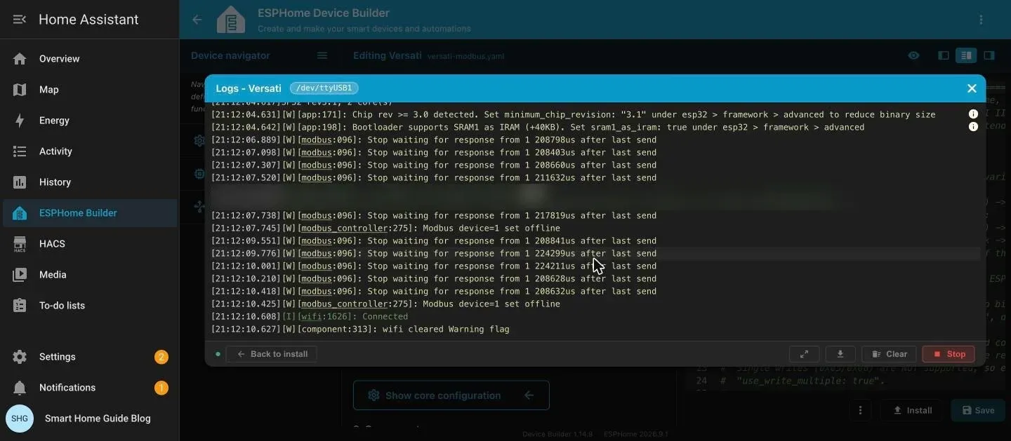
When the write ends, the dialog switches to the live log on its own. A bare board with nothing on the RS485 side prints Stop waiting for response from 1 over and over, followed by Modbus device=1 set offline. That's expected: nobody answers yet. Two yellow notes about chip revision 3.1 are only hints for shrinking the binary, so ignore them. The line you're waiting for is wifi: Connected.
On a computer instead of the Pi you may need a USB driver (CH340 on the board in my photos, CP210x on many others). If flashing stalls at "Connecting", hold the BOOT button on the ESP32 until it starts.
Every later update goes over Wi-Fi: click Install > On the network. Before the first USB install the dialog warns that the firmware can't reach the device yet, which is expected.
6. Install at the heat pump
With the heat pump off at the breaker, connect the twisted pair to the BMS port, mount the boards, plug in the USB supply and switch the heat pump back on.
7. Add it to Home Assistant
You don't have to wait for the heat pump to do this, and I'd rather you didn't. Adding the board while it's still on your desk proves that the Wi-Fi details and the API key work before you carry anything to the unit.
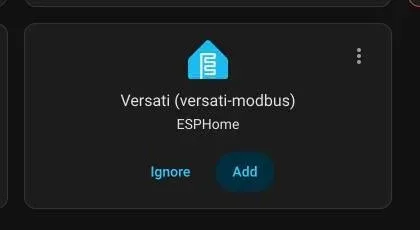
Within seconds of the first boot, Home Assistant lists the board under Settings > Devices & services, in the Discovered section, as Versati (versati-modbus) from ESPHome. Click Add (older versions label it Configure), then Submit. I wasn't asked for the encryption key. A device built by the ESPHome Builder app hands its key over by itself; one compiled somewhere else asks you to paste it here. The last dialog, Name and assign, offers a device name and an area, and Skip and finish is fine.
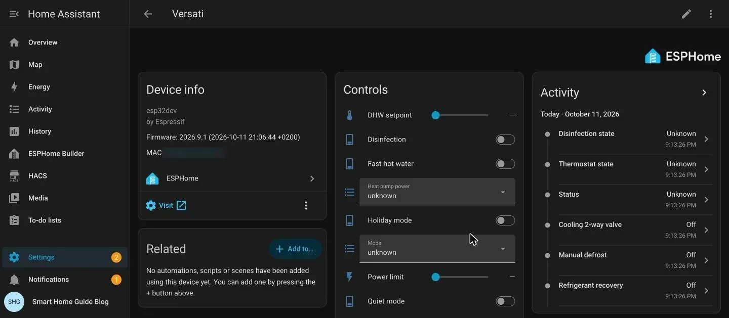
All entities land on one device page: 167 of them, which matches the 24 sensors, 33 setpoints, 9 selects, 23 switches, 76 binary sensors and 2 buttons listed at the top. Until the bus is wired they all read Unknown, and the Modbus warnings keep scrolling in the ESPHome log. That's the correct picture for a board with no heat pump behind it.
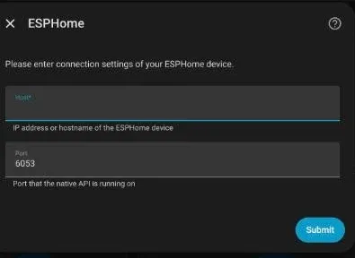
If nothing is discovered, for example because the ESP32 sits on another VLAN, use Add integration > ESPHome instead: enter the device's IP address, keep port 6053, and paste the same key.
Why Is the Config Built This Way?
Three decisions make the difference between a demo and something you can leave running.
Writes use function 0x10 and 0x0F only. Gree's document lists four function codes: read coils (0x01), read registers (0x03), write multiple coils (0x0F) and write multiple registers (0x10). There is no single-register (0x06) or single-coil (0x05) write. ESPHome uses single writes by default, which is a likely cause of the "reading works, writing does nothing" reports in community threads. Every writable entity in this config sets use_write_multiple: true.
Two polling speeds. Live values poll every 15 seconds. Setpoints and configuration flags, which rarely change, poll every 2 minutes through a second controller at the same address. The bus stays quiet and the ESP's log stays readable.
Signed temperatures. Outdoor and refrigerant temperatures go below zero, so they are read as signed words. Read as unsigned, a frosty morning shows up as 6,553 C.
Which Key Registers Matter Most?
| Address | Type | What it is | Notes |
|---|---|---|---|
| Word 2 | R/W | Mode | 1 heat, 2 hot water, 3 cool + hot water, 4 heat + hot water, 5 cool |
| Word 10 | R/W | Water heating setpoint | 20-60 C (high-temp units) |
| Word 13 | R/W | Hot water tank setpoint | 40-80 C |
| Word 42 | R/W | On/off | 0xAA on, 0x55 off |
| Word 43 | R/W | Power limit | 0-10 kW, sent as value x 10 |
| Word 44 | W | Error reset | write 1 |
| Word 117 | R | Unit status | 1 cool, 2 heat, 6 hot water, 8 off |
| Word 118 | R | Outdoor temperature | |
| Words 125 / 127 | R | Water out / water in | |
| Word 128 | R | Tank temperature | |
| Word 143 | R | Compressor frequency | Hz |
| Coil 21 | R/W | Quiet mode | |
| Coil 22 | R/W | Weather-dependent mode | |
| Coil 80 | R | Compressor running | |
| Coils 64-191 | R | Errors and protections | full list in the config |
How Do You Check the Temperature Scale?
Gree's document says temperatures are transmitted in whole degrees. Community builds (koelec, peca2345) divide them by ten. The config defaults to dividing by ten (temp_scale: "0.1"). Compare Outdoor temperature in Home Assistant with the controller's display:
- They match: you are done.
- Home Assistant shows a tenth of the real value: set
temp_scale: "1"and reinstall wirelessly.
Then let it run read-only for a few days. Watch flow and return temperatures, compressor frequency during a heating cycle and the status text. If those make sense, the link is solid.
How Do You Troubleshoot Problems?
| Symptom in the ESPHome log | Likely cause | Fix |
|---|---|---|
| No response / timeout from slave 1 | TX/RX or A/B swapped, wrong address | Swap TX/RX, then A/B; check Address in the controller |
| Modbus CRC Check Failed | Noise or termination | Shielded cable, toggle the 120 ohm terminator, shorten the run |
| Readings fine, writes ignored | Single-register writes | Keep use_write_multiple: true on every writable entity |
| Mode change does nothing | Unit is running | Turn the unit off, change mode, turn it on |
| No response with a MAX485 board, EN not wired | Direction pin never switches to send | Wire EN to D4 and uncomment flow_control_pin: GPIO4 |
| Every entity Unknown, log says Modbus device=1 set offline | Nothing answers on the bus yet | Normal on a desk; wire the board to the BMS port, then check Address and A/B |
| Values are 10x off | Scale | Change temp_scale |
| Error code 0x02 or 0x03 in the log | Illegal address or data | A register outside the documented range or a value outside its limits |
How Do You Write to the Unit Safely?
Writes change how a heat pump runs, so a few rules from Gree's document are worth respecting:
- Change mode only when the unit is off. Gree states mode changes while running are ineffective. Turn it off, change mode, turn it back on.
- Settings persist after 30 minutes. Changes apply immediately, but the controller saves them to memory after half an hour. If power drops in between, the old value comes back.
- The hot water setpoint is ignored while disinfection is running.
- Start with small changes. Nudge the water setpoint by a degree or two, watch a full cycle, then automate.
Which Two Automations Are Worth Adding?
Get notified on any fault. The combined Fault entity rolls up communication errors, pressure protections, flow protection and irrecoverable states.
automation:
  - alias: "Heat pump fault"
    triggers:
      - trigger: state
        entity_id: binary_sensor.versati_fault
        to: "on"
        for: "00:02:00"
    actions:
      - action: notify.mobile_app_your_phone
        data:
          title: "Heat pump fault"
          message: "Versati reports a fault. Check the controller display."
Store solar surplus as hot water. If you have a sensor for grid export, raise the tank setpoint while you export and drop it back afterwards. Replace sensor.grid_export_power with your own entity.
automation:
  - alias: "Solar surplus: boost hot water"
    triggers:
      - trigger: numeric_state
        entity_id: sensor.grid_export_power
        above: 2000
        for: "00:10:00"
    actions:
      - action: number.set_value
        target:
          entity_id: number.versati_dhw_setpoint
        data:
          value: 55

  - alias: "Solar surplus ended: normal hot water"
    triggers:
      - trigger: numeric_state
        entity_id: sensor.grid_export_power
        below: 200
        for: "00:15:00"
    actions:
      - action: number.set_value
        target:
          entity_id: number.versati_dhw_setpoint
        data:
          value: 48
Entity IDs depend on the names in your config; check them on the device page.
FAQ
Can I skip the ESP32 and use a USB RS485 adapter? Yes, if your Home Assistant server sits near the controller. Several users in the Home Assistant community thread run a USB adapter on a Raspberry Pi with the built-in Modbus integration. The ESP32 route wins when the server is elsewhere, because only Wi-Fi has to reach the plant room.
Does this replace the Gree+ app? No, both work side by side. The Wi-Fi module and the BMS port are separate interfaces.
Can I change the operating mode from Home Assistant? Yes, through the Mode select, but only while the unit is off. That is Gree's rule, not a limitation of the config.
Will this void my warranty? The BMS port is a documented interface for building management systems, and nothing inside the unit is modified. Warranty terms differ by country and installer, so ask yours if in doubt.
Does it work with Versati II or IV? Not as is. Their register maps differ; use the Modbus document for your model.
Primary documents used
- Gree, "MODBUS [VERSATI III]", original instructions ver. 01, 2021-08-09 (register map, BMS port pinout, bus settings)
- Gree, Versati III Split / All-in-One service manual (controller wiring, CN4)
- koelec/EspHome-Gree: ESPHome interface for Versati III, BMS port location
- roeldie/ESPHome-modbus-heatpump-cooper-and-hunter-UNITERM-3: fork carrying the Versati III Modbus document
- Home Assistant Community: Gree Versati III air to water heat pump
- ESPHome Modbus Controller documentation
Sources & References
- ESPHome - Modbus Controller esphome.io
- ESPHome - Modbus Component esphome.io
- Home Assistant - ESPHome home-assistant.io